Schematic 555 Timer Circuit Diagram / The 555 Timer Based Alarm Circuit With Automatic Reset And Multiple Download Scientific Diagram / Here is a simple and interesting hobby circuit that can be made using the popular 555 timer ic.
Schematic 555 Timer Circuit Diagram / The 555 Timer Based Alarm Circuit With Automatic Reset And Multiple Download Scientific Diagram / Here is a simple and interesting hobby circuit that can be made using the popular 555 timer ic.. It has been redesigned, improved, and reconfigured in many ways, yet the. There are simple circuits for beginners and advanced engineers. The 555 timer is a simple integrated circuit that can be used to make many different electronic circuits. Suitable for various test circuits. You can for example use it to reverse the direction of a robot when it bumps into a wall.
The following schematic shows two additions to the basic 555 timer circuit. It has been redesigned, improved, and reconfigured in many ways, yet the. As the name indicates, only one state is stable and the other one is called unstable or quasi stable state. Its name is derived from three 5k ohm resistors ,connected in series used in it.the timer ic can produce required waveform accurately. Here you have separate on and off buttons to control an led.
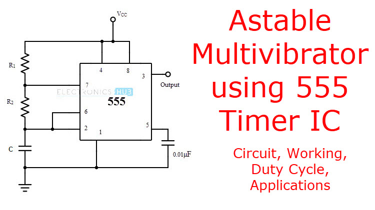
Astable Multivibrator Utilizing 555 Timer Circuit Obligation Cycle Purposes Electrician World News from www.electronicshub.org To understand the basic concept of the timer let' s first examine the timer in block form as in figure 1. In this circuit, after you press the button once, the led will light up then turn off. 555 timer ic remains in stable state until the external triggering is applied. Daman shah june 5, 2021. The reset input current draw illustrates the need for a current limiting resistor as shown in some of the preceding circuits. Simple 555 timer circuits & projects. See more ideas about timer, electronics circuit, circuit. Operation of the circuit is when the power supply to the circuit.
As we know 555 timer ic is one of the commonly used ic among students and hobbyists.
In this category, we have handpicked some really useful 555 timer circuits which will be interesting to electronics engineering students and hobbyists alike. Various light actuator and relay driver circuits are also further enclosed. The reset input current draw illustrates the need for a current limiting resistor as shown in some of the preceding circuits. The 555 timer ic is an integral part of electronics projects. You can for example use it to reverse the direction of a robot when it bumps into a wall. As the name indicates, only one state is stable and the other one is called unstable or quasi stable state. 555 timer ic remains in stable state until the external triggering is applied. After one minute of time duration, the led will automatically turn on. Two tone generator circuit using 555. 555 timer bistable example circuit. An ic timer ic 555 is a number of major equipment. The 555 timer is a simple integrated circuit (ic) that can be used in electronic circuits, projects, and a variety of applications like timer, pulse oscillator, delays, flip flop, etc Figure 1 is the pinout and functional block diagram for the 555 timer ic.
Here, we take a look at some 555 timer circuits based on the ic. If a 10uf timing capacitor is used, calculate the value of the resistor required to produce a minimum output time delay of 500ms. Two tone generator circuit using 555. The standard 555 timer ic is made of 2 diodes. Monostable multivibrator (mmv) mode of 555 timer ic is also called single shot mode.
Use A 555 Timer As A Switch Mode Power Supply Edn from www.edn.com Various light actuator and relay driver circuits are also further enclosed. There are simple circuits for beginners and advanced engineers. A collection of 555 circuits using the 555 timer as an astable oscillator with different duty cycles. Independently manufactured by more than 10 manufacturers, still in current production, and almost 40 years old, this little circuit has withstood the test of time. Its name is derived from three 5k ohm resistors ,connected in series used in it.the timer ic can produce required waveform accurately. Once this switch is pushed, the circuit pulls its output to a. The 555 timer ic is an integral part of electronics projects. 555 timer circuits (133) browse through a total of 133 555 timer circuits and projects including the timer's datasheet.
An external triggering is required for transition from stable to unstable state.
Here is a simple and interesting hobby circuit that can be made using the popular 555 timer ic. 555 timer circuits (133) browse through a total of 133 555 timer circuits and projects including the timer's datasheet. This is a simple noise generator circuit. 555 timer was first introduced by signetics corporation in 1971 as se555/ne555. Daman shah june 5, 2021. This project uses a static sensitive part, the cmos 555. A monostable 555 timer is required to produce a time delay within a circuit. An ic timer ic 555 is a number of major equipment. Once this switch is pushed, the circuit pulls its output to a. For 5 min, 10 min and 15 min you just have to change the resistor value (r 1). Monostable multivibrator (mmv) mode of 555 timer ic is also called single shot mode. The 555 timer is a simple integrated circuit (ic) that can be used in electronic circuits, projects, and a variety of applications like timer, pulse oscillator, delays, flip flop, etc This circuit uses very basic components like 555 timer and 4017 counter.
From our earlier discussions we know that for a 555 in the delay timer mode, the delay could be accurately managed through a single external resistor and one capacitor. The next diagram shows the basic current consumption of 555 timer chips from different manufacturers. The 555 ic timer circuit above shows a very straightforward design where the ic 555 forms the central controlling part of the circuit. Here is a simple and interesting hobby circuit that can be made using the popular 555 timer ic. Once this switch is pushed, the circuit pulls its output to a.
File Ne555 Bloc Diagram Svg Wikimedia Commons from upload.wikimedia.org The 555 timer starts timing when switched on. It has been redesigned, improved, and reconfigured in many ways, yet the. Independently manufactured by more than 10 manufacturers, still in current production, and almost 40 years old, this little circuit has withstood the test of time. Some devices will not function properly if the current to the threshold input is not restricted. Here you have separate on and off buttons to control an led. 555 timer circuits (133) browse through a total of 133 555 timer circuits and projects including the timer's datasheet. As the name indicates, only one state is stable and the other one is called unstable or quasi stable state. This circuit can be used as rain sensor, water overflow sensor or as a water level sensor.
Once this switch is pushed, the circuit pulls its output to a.
This project uses a static sensitive part, the cmos 555. Learn one of several 555 timer astable multivibrator configurations; As the name indicates, only one state is stable and the other one is called unstable or quasi stable state. Various light actuator and relay driver circuits are also further enclosed. Adjustable on off timer(using 555 astable mode) in this circuit a timer with cyclic on off operations is designed. With this information you will learn how how the 555 works and will have the experience to build some of the circuits below. This circuit uses very basic components like 555 timer and 4017 counter. The 555 ic timer circuit above shows a very straightforward design where the ic 555 forms the central controlling part of the circuit. As we know 555 timer ic is one of the commonly used ic among students and hobbyists. This circuit can be used as rain sensor, water overflow sensor or as a water level sensor. Independently manufactured by more than 10 manufacturers, still in current production, and almost 40 years old, this little circuit has withstood the test of time. This is a simple noise generator circuit. The standard 555 timer ic is made of 2 diodes.
Or separate the on and off switch for a machine 555 timer schematic. Here is a simple and interesting hobby circuit that can be made using the popular 555 timer ic.


0 Komentar